Design guidelines
Designing an element yourself for us to print? These guidelines help you take the possibilities of robotic printing into account from the start. In doubt? We are happy to take a look.
Ten points for a printable design
Robotic printing offers a lot of freedom of form. These points show what to look out for, so your design can be printed without detours.
Dimensions
A single printed element is up to 3 x 3 x 3 metres. If your design is larger, we split it into segments that form one whole on site.
Built in layers
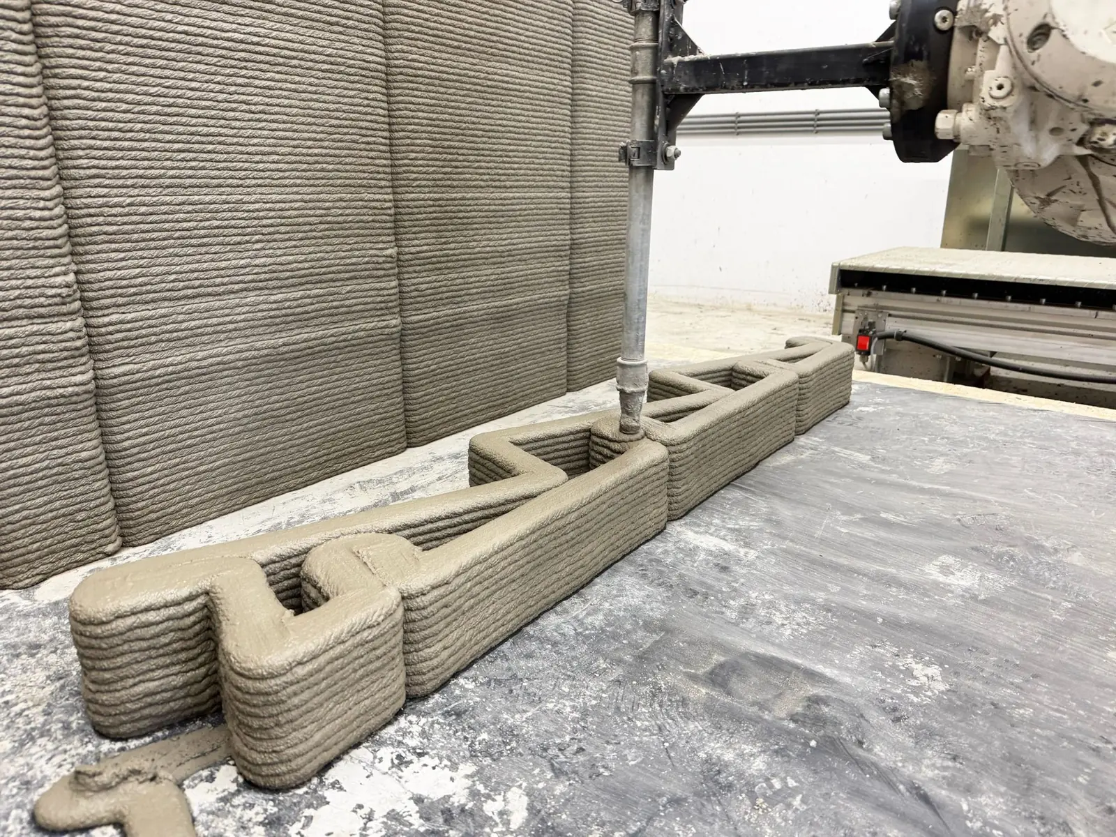
The robot builds the element layer by layer, from bottom to top. Each layer rests on the one below. Design straight up or from wide to narrow.
Overhang
A wall can lean outwards to a limited extent without support. How far depends on the width and height of the printed layer. For larger overhangs we adapt the shape or the print direction.
Corners and curves
A strand of mortar cannot form a razor-sharp corner. Give corners a radius. The wider the printed layer, the larger that radius needs to be.
Continuous print path
The best result comes from a closed shape the robot can print without interruption. Joints and crossings are possible, but need enough overlap between layers.
Hollow structure
Many elements are hollow, with internal walls that make the whole strong. That way we only use material where it is structurally needed, usually without reinforcement.
Sloped tops
We print a sloped or free-form top as a series of small steps, or with layers that follow the shape. This also allows slopes and curved surfaces.
Splitting and joining
We make large objects in numbered segments. Consider the joints, transport and lifting points in your design, so the elements can be placed safely.
Openings and inserts
Openings for pipes, drainage or connections can be included in the design if needed. Inserts such as anchors or lifting eyes are placed during or after printing.
Surface and finish
By default, the print lines remain visible. That gives a recognisable texture and good grip. A smoother finish or a pattern is also possible.
From design to printed element
Sketch or model
Send a sketch, drawing or 3D model.
Review
We check the design against these guidelines and make it printable.
Test piece
Where needed we first print a test piece or detail.
Production
Then production follows in our robot lab.
In short
Exact values such as layer thickness, overhang and tolerances depend on the design and the material. We agree these with you per project.
| Maximum size per element | 3 x 3 x 3 metres |
|---|---|
| Material | Special mortars |
| Reinforcement | Not needed in most applications |
| Surface | Visible print lines, optionally smoother or patterned |
| Submission | Sketch, 2D drawing or 3D model |
What shall we build together?
Municipality, water authority or contractor with a challenge in public space? We are happy to help, from feasibility to delivery.